


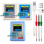

High Quality Brand New LCR-T4 LCR-MF9 TC1 T7 ESR Meter Transistor Tester Diode Triode Capacitance SCR Inductance with Test Took
Price range: 593.60৳ through 1,162.00৳
| Color |
Box-LCR-T4 ,Buckle-LCR-T4 ,LCR-MF9 ,LCR-T7 ,LCR-TC1 |
|---|
♦ Disclaimer: AliMarket একটি ক্রস বর্ডার শপিং সার্ভিস প্রোভাইডার। আমাদের মূল লক্ষ্য বর্ডার বাধা পেরিয়ে আপনাকে কাঙ্ক্ষিত পণ্য এনে দেওয়া। AliMarket এ প্রদর্শিত প্রোডাক্ট বিভিন্ন থার্ড পার্টি শপিং ওয়েবসাইট থেকে সংগৃহীত। অর্থাৎ AliMarket সরাসরি কোন পণ্যের সেলার বা ম্যানুফ্যাকচারার নয়। তাই AliMarket কোনো প্রাসঙ্গিক, জামানত বা যৌথ দায় নিতে বাধ্য নয়। তবে গ্রাহক স্বার্থ রক্ষার্থে শপিং ওয়েবসাইটের রিফান্ড পলিসি অনুসারে AliMarket বিফর এবং আফটার সেলস সার্ভিস দেয়।
- Hign-concerned Chemical: None
- Model Number: LCR-T4/LCR-MF9/LCR-TC1/LCR-T7
- Brand Name: RUIBOZHI
- Origin: Mainland China
- Certification: CE
- DIY usage scenarios: ELECTRICAL
- Display mode: Digital display
- DC Voltage: 3.7v
- Measure resistance range: 0.01-50MΩ
- Measure capacitance range: 25pF-100mF
- Measure the range of inductance: 0.01mH-20H
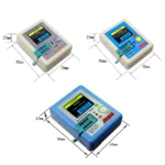
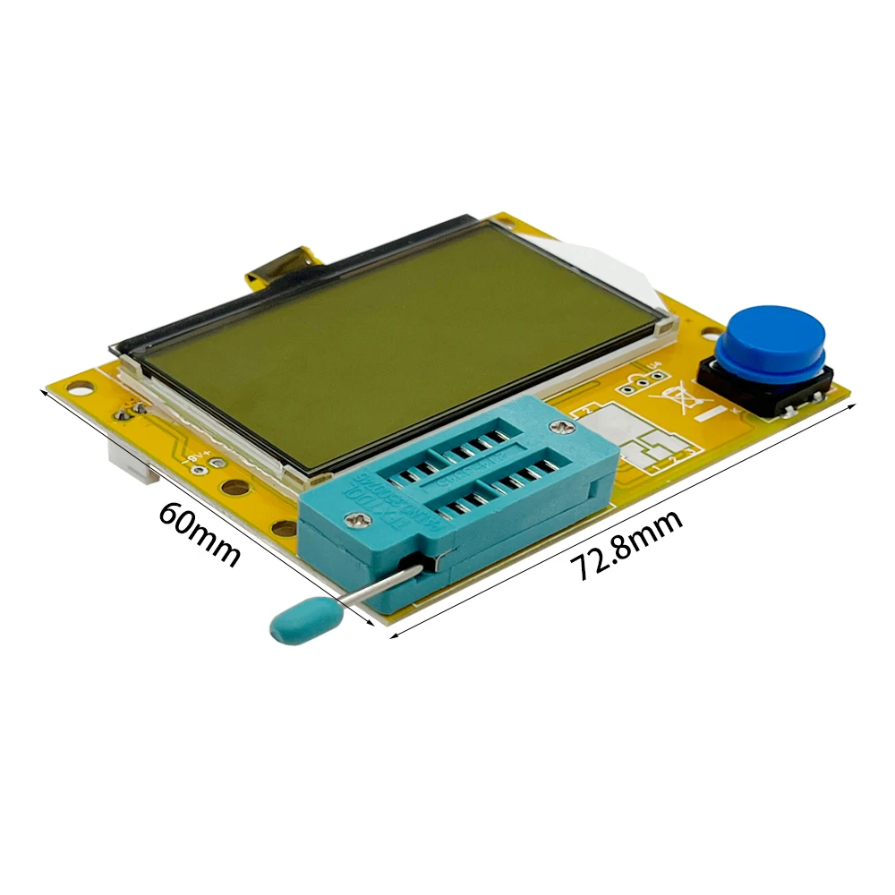
- Specification: 70*90*28MM

If the quality problem of the product is found after receiving the express, please do not open the dispute at will. Please contact our after-sales customer service to solve it in a timely manner. Thank you for your support and understanding!
2025 New Transistor Tester
Functions than the previous version, increased the shutdown time countdown display
KAA zone needs to be opened manually, which reduces the damage of the instrument.
Optimize some parameters
Video demonstration in English, and precautions
http://www.mcustart.cn/zl/MF9N/MF9.html
Function
*Built-in 300MAH 4.2V lithium battery, rechargeable.
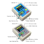
*TFT 1.8-inch color screen display, graphical display of various parameters
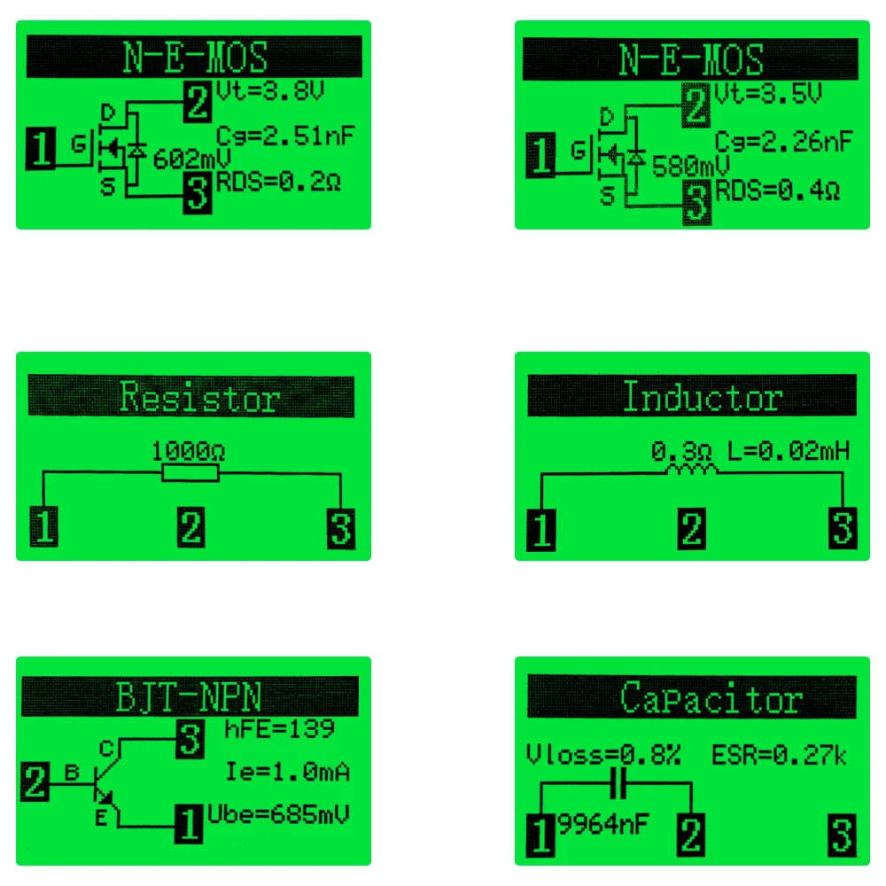
*Automatically detects NPN and PNP transistors, N-channel and P-channel MOSFETs, IGBTs, diodes (including double diodes), thyristors, transistors, resistors and capacitors.
*Automatically detects the pinouts of components and graphically displays them on a color screen.
* Can detect infrared code (support NEC format infrared remote control)
*Transistors, MOSFET protection diodes, etc. can be detected amplification coefficient and the base of the determination of the forward bias voltage of the emitter transistor
*Depletion type and enhancement type MOSFETs can be distinguished.
*MOSFETs with gate threshold voltage and gate capacitance can be measured.
*Supports measurement and symbol display of two resistors with a resolution of 0.1 Ohm and a maximum measurement value of 50M Ohm.
*VOSS and ESR can be displayed for capacitors higher than 10UF.
*Measures inductance for resistances below 2100 ohms and DC resistance for inductances below 10UH.
*Higher test speed, expiration date component test: in 2 seconds (except in the larger capacitors, large capacitance measurement also need a longer time)
* Equipped with a calibration needle, calibrated to test small resistors more accurately
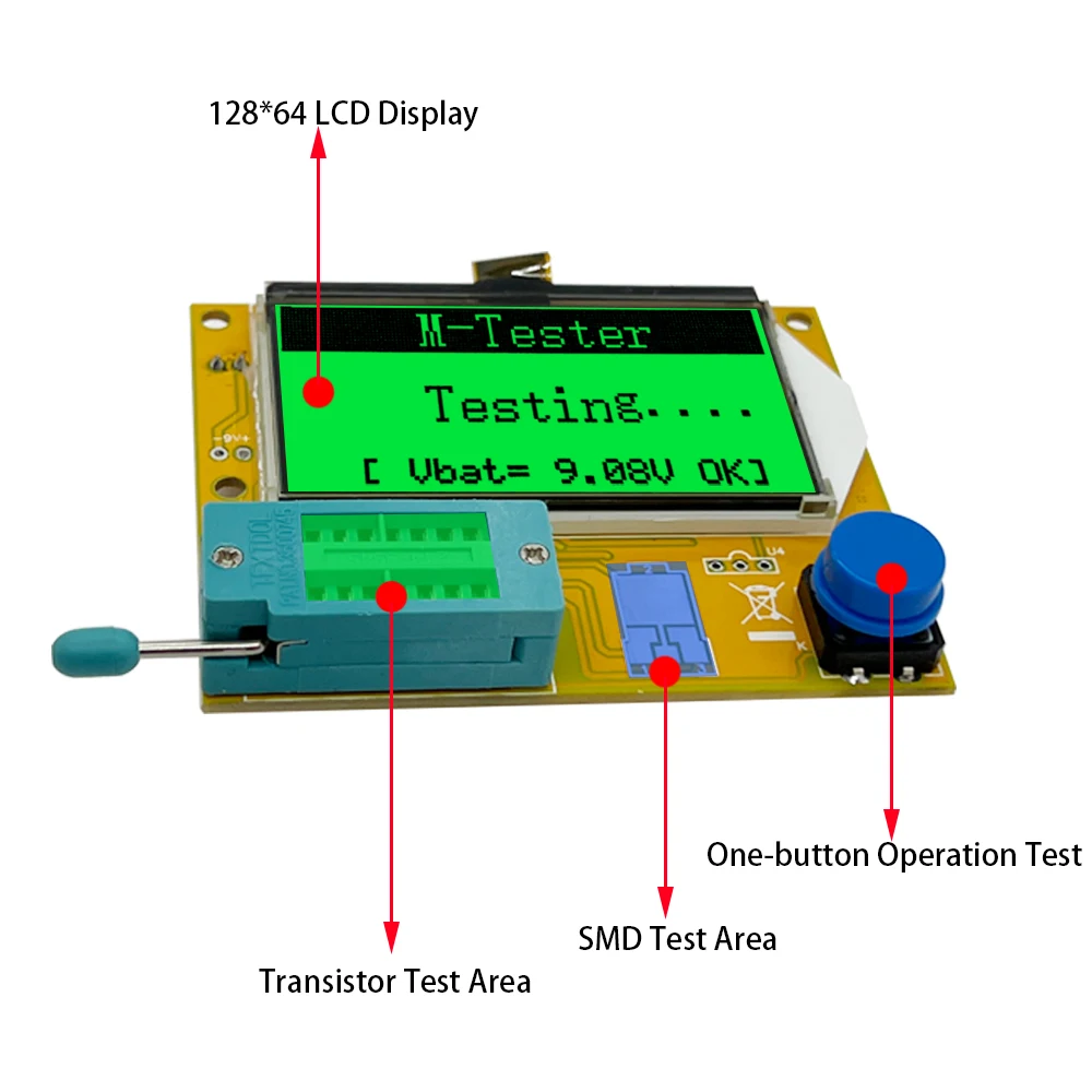
*One button operation, power on test
*Power consumption off mode: less than 20 nA
*Automatic shutdown function, saving battery energy, improve the duration.
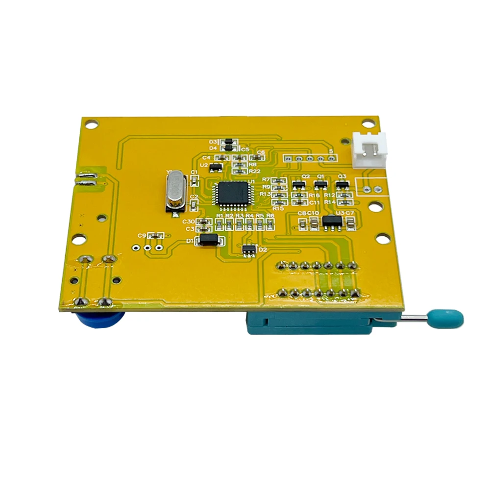
Product Accessories:
Tester main unit X1
Test cable X3
USB cable X1


Transistor tester:
Automatic detection of NPN and PNP bipolartransistors.N-channel and P-chmnnel
MOSFETs,JFETs diodes(including double Diodes)
N.and P-IGBTS, resisiors, Inductors, capacitors, thyristors,triacand battery (0 .1-4.50V)
Automatie detection of zener diode (0.01-20v)Self test with automatic calibration
IR decoder:
Support Hitachi lR coding
-lR waveform display
Other:
Measurement results using TFT graphic display(160×128)Auto Power Off(Timeout Settable)
Built-in rechargeable Li-ion Battery
Li-ion Battery voltage detection – 160×128 TFT display
Warning: Built-in Li-ion Battery, it is strictly prohibited the testerimmersed in water, or near a heat source!
Warning: For your personal safety, please strictly comply withthe use of Li-ion Battery specifications and precautions!
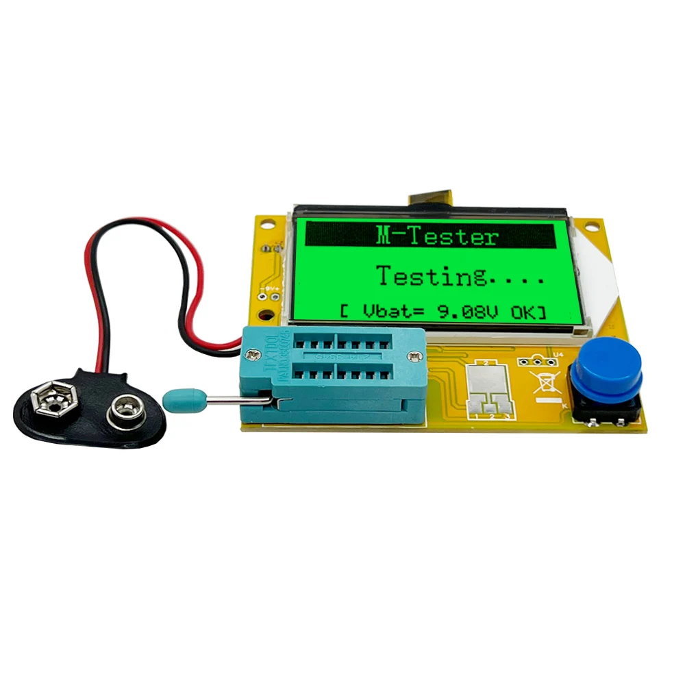
Power on:
In the power off state, short press themultifunction key, the tester is turnedon and automatically measured.

Power on & measurement interface
Detect transistor:
ln the power off state or the test is completed, put the test element into the transistor test area oftest seat, and press the locking handle, short press the multifunction key, the tester automaticallymeasure, graphical display of measurement results when testing is complete.
Warning: Always be sure to DISCHARGE capacitors before connectingthem to the tester! The tester may be damaged before you have switched it on!
Warning: Always be sure to DISCHARGE capacitors before connectingthem to the tester! The tester may be damaged before you have switched it on!
Warning: We do not recommend using the tester to measure thebattery! The battery voltage must be less than 4.5V, otherwise the testermay be damaged!


Detect Zener Diode:
When the device is turned off or the test is completed, put the Zener diode into the Zener diodetest area, press the locking handle, and briefly press the multi-function button.
Note: Do not put components in theTransistor test area, otherwise theZener diode cannot be tested!

Note: Do not put components in theTransistor test area, otherwise theZener diode cannot be tested!
lR decoder:
After the component test is completed, point the infrared remote control at the "IR" test hole of the tester. press the remote control button, the tester will display the user code and data code after successful decoding, and display the corresponding infrared waveform.
lf the decoding fails or the decoding fails, the user code and data code cannot be displayed.Atthis time, if you are in the tester interface, you cannot enter the infrared decoding interface. If youare in the infrared decoding interface, the last successful decoding information will still be displayed.

Note:This decoder only supportsinfrared encoding in Hitachi format.Other formats of infrared encodingare not supported
Automatic calibration:
Short-circuit three test sockets, short press the multi-function button, and the tester willautomatically calibrate.
During the calibration process, there is no need to perform other operations except to disconnectthe short wire according to the prompts.

Shutdown:
Automatic shutdown after timeout
When the component test is completed or the infrared decoding is completed, and the automaticshutdown time is reached, the tester will automatically shut down (overtime 30 seconds) Standby power consumption is 0 UA after shutdown.
Battery voltage measurem:
Before each component measurement, the built-in lithium battery voltage will be detected anddisplayed. When the battery voltage is less than 3.1V, it will be forced to shut down. Pleasecharge it at this time.

Battery charging circuit:
The charging interface is a standard Micro USB interface, please use an external 5V powersupply or USB power supply for charging.
Note: When the charging indicatoris red, it means charging, and greenmeans charging is complete.
FAQ:
The charging interface is a standard Micro USB interface, please use an external 5V powersupply or USB power supply for charging.
Question:can not power on
Cause:Lithium battery is low
Solution:Please charge until the light turns green
lnaccurate:Please re-calibrate
measurements:Please re-calibrate
Known errors and unsolved problems:
1.The current amplication factor of germanium transistors can be measured too high becauseof the high residual current. In this case the basis emitter voltage will be very low.
2.Capacity value in reverse direction for Power Schottk Diodes such as MBR3045PT can not be measured, if only one diode is connected.The reason is a too big residual current of thisdiode. Sometimes the measurement is possible by cooling down the device (with cooling sprayfor example).
3.The diode function of a triac gate can not be examined.
4.The Source and Drain pins can not be detected correctly with JFET's. The reason is thesymmetrical structure of this semiconductors. You can notice this problem with the elect,that the display shows the same layout with the same pal rameters, if the Source and Drain pinsare swapped.
5. The output current of the tester is 6MA/voltage <5V.High-power IGBTs, thyristors, andDarlington tubes that require higher current/higher voltage drive may not be measured. Air corecoils and power inductors cannot directly measure inductance. It is recommended to try seriesconnection. Appropriate color ring inductance test, capacitors below 20PF, it is recommended totest a 20PF capacitor


3. On or Off voltage of the FET must be less than 5V
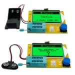
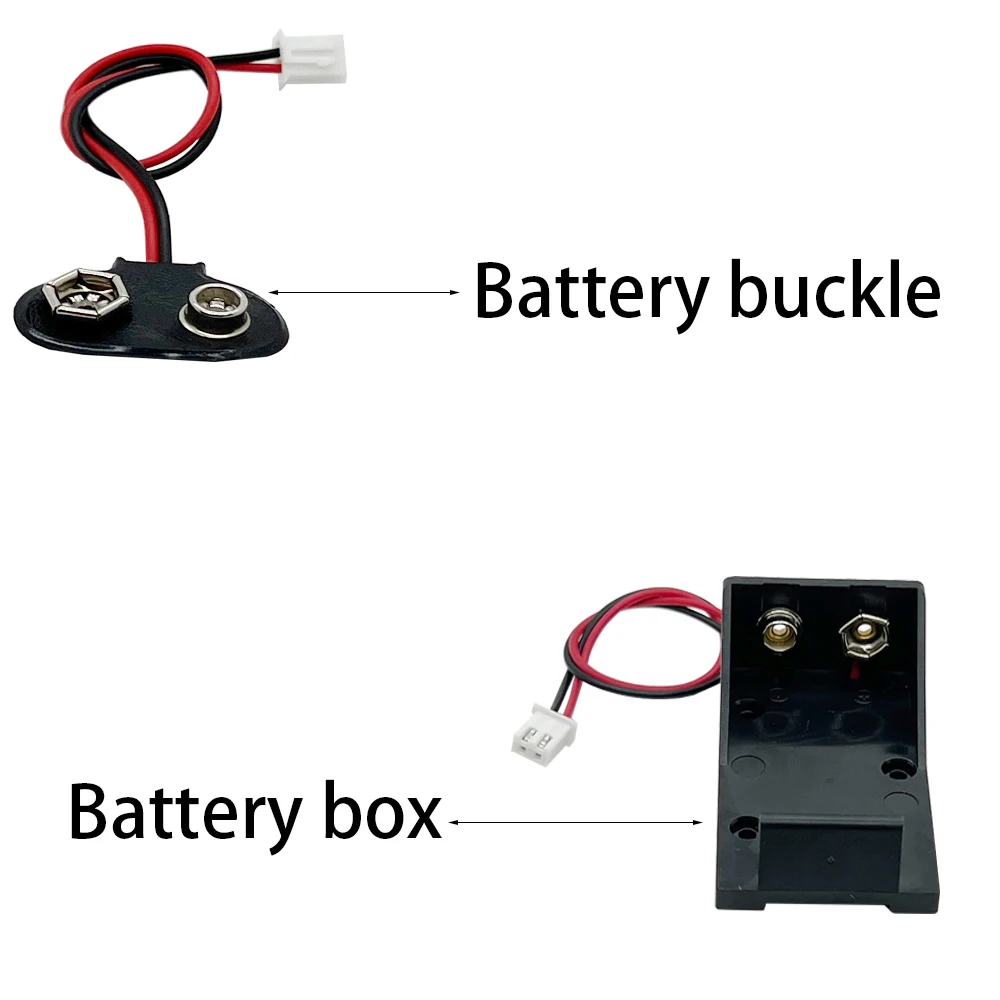
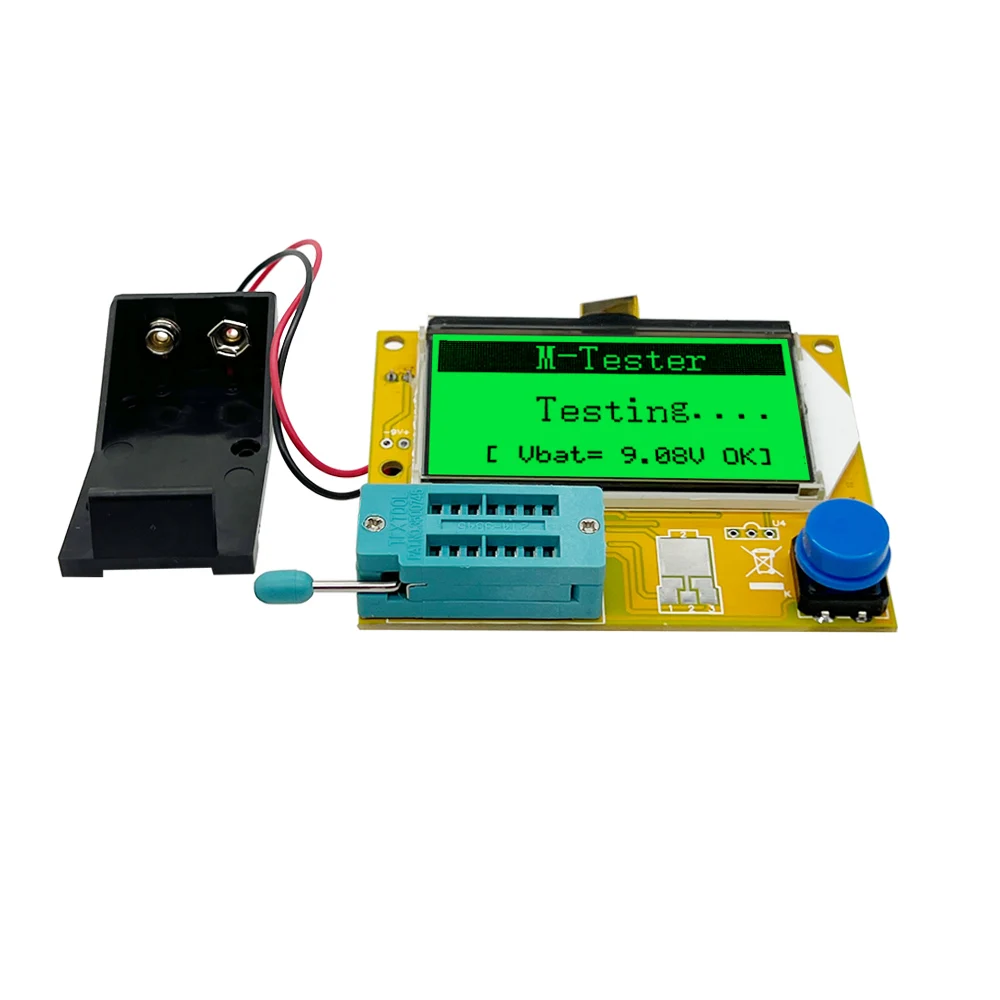
• Using 9V battery (Not included)
• 128*64 big Backlight LCD display,only 2mA when stand by.
• Inductors, capacitors , diodes, dual diode , mos, transistor, SCR , the regulator, LED tube , ESR,
• Resistance,Adjustable potentiometer
• Resistance : 0.1 ohm resolution, maximum 50M ohm
• Capacitor : 25pf -100,000 uf
• Inductors : 0.01mh-20H
• Automatic detection of NPN and PNP transistors, n-channel and p-channel MOSFET,
diode (including double diode), thyristor, transistor, resistor and capacitor and other components
• Automatic test the pin of a component, and display on the LCD
• Can detect the transistor, MOSFET protection diode amplification coefficient
and the base to determine the emitter transistor forward biased voltage
• Measure the gate and gate capacitance of the MOSFET threshold voltage
• Use 12864 liquid crystal display with green backlight
Specifications: For you reference
1. One click operation, automatically turning off the power.
2. The shutdown current is only 20nA and supports battery operation.
3. Automatic detection of PNP and NPN bipolar transistors, N, P channel MOSFETs, JFETs, diodes, dual diodes, thyristor thyristors.
4. Automatically detect pin layout.
5. Measure the current amplification coefficient and threshold voltage of the emission junction of a bipolar transistor.
6. Darlington transistors can be identified by high threshold voltage and high current amplification coefficient.
7. Detection of protective diodes for bipolar transistors and MOSFETs.
8. Measure the threshold voltage and gate capacitance value of MOSFETs.
9. Supports the measurement and symbol display of two resistors, with up to four digits and units displayed. The displayed resistance symbol shows the connected tester probe numbers (1-3) at both ends. So Potentiometer can also measure. If the Potentiometer is adjusted to one end of it, the tester cannot distinguish between the pins in the middle and at both ends.
10. The resolution of resistance measurement is 0.1 ohms, with a maximum measurement value of 50M ohms.
11. A capacitor can be detected and measured. Display the highest four digits and units. The value can range from 25pf to 100mF. Resolution up to 1 pF
12. It is possible to measure the Equivalent series resistance (ESR) capacitance of capacitors with a value above 10UF. The resolution is 0.01 ohms and displays two digit values.
13. It is possible to display symbols in the correct direction for two diodes. In addition, the positive voltage drop is displayed.
14. The LED is detected as a diode, and the forward voltage drop is much higher than Normal height. Double light-emitting diodes are detected as double diodes.
15. Zener diodes can be detected if the reverse breakdown voltage is below 4.5V. This will be displayed as two diodes, which can only be determined by voltage. The symbols around the diode of the probe are the same, in this case, you can identify the true anode of the diode by the threshold voltage near 700mV!
If there are more than 3 diode type parts detected, establish the number of diodes and display another failed message. This will only occur if the diode is connected to all three probes and at least one is a type diode. In this case, you should only connect two probes and initiate the measurement again, one after the other.
16. Measure the capacitance value of a single diode in the opposite direction. Bipolar transistors can also be measured if you connect the base to the collector or emitter.
17. Only one measurement is needed to find the connection of the entire bridge.
18. Capacitors with values below 25pf are usually undetectable, but can be connected in parallel with a diode or at least 25pf capacitor. In this case, you must subtract the part of the parallel capacitance value.
19. A resistance below 2100 ohms will measure inductance. The range will exceed 20H from 0:01mH, but the accuracy is not good. The measurement results only show a single component connection.


Reviews
There are no reviews yet.